1.using netcut software, dont even try to cut your server ip and yours, or you will be disconnected
2. winarpattacker, scan the connected network and choose the target
2.baned gateway
3. flooding
that's all maybe it is can help you
Thursday, April 8, 2010

Tap Changer (Perubah Tap) Pada Transformator
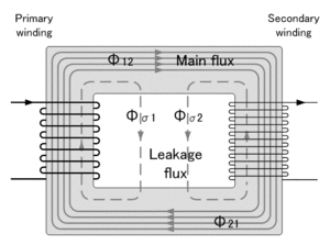 Tap changer adalah alat perubah perbandingan transformasi untuk mendapatkan tegangan operasi sekunder yang lebih baik (diinginkan) dari tegangan jaringan / primer yang berubah-ubah.
Untuk memenuhi kualitas tegangan pelayanan sesuai kebutuhan konsumen (PLN Distribusi), tegangan keluaran (sekunder) transformator harus dapat dirubah sesuai keinginan. Untuk memenuhi hal tersebut, maka pada salah satu atau pada kedua sisi belitan transformator dibuat tap (penyadap) untuk merubah perbandingan transformasi (rasio) trafo.
Ada dua cara kerja tap changer:
1. Mengubah tap dalam keadaan trafo tanpa beban. Tap changer yang hanya bisa beroperasi untuk memindahkan tap transformator dalam keadaan transformator tidak berbeban, disebut “Off Load Tap Changer” dan hanya dapat dioperasikan manual (Gambar 1).
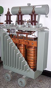
2. Mengubah tap dalam keadaan trafo berbeban. Tap changer yang dapat beroperasi untuk memindahkan tap transformator, dalam keadaan transformator berbeban, disebut “On Load Tap Changer (OLTC)” dan dapat dioperasikan secara manual atau otomatis (Gambar 2).

Transformator yang terpasang di gardu induk pada umumnya menggunakan tap changer yang dapat dioperasikan dalam keadaan trafo berbeban dan dipasang di sisi primer. Sedangkan transformator penaik tegangan di pembangkit atau pada trafo kapasitas kecil, umumnya menggunakan tap changer yang dioperasikan hanya pada saat trafo tenaga tanpa beban.
OLTC terdiri dari :
1. Selector Switch
2. diverter switch
3. transisi resistor
Untuk mengisolasi dari bodi trafo (tanah) dan meredam panas pada saat proses perpindahan tap, maka OLTC direndam di dalam minyak isolasi yang biasanya terpisah dengan minyak isolasi utama trafo (ada beberapa trafo yang compartemennya menjadi satu dengan main tank).
Karena pada proses perpindahan hubungan tap di dalam minyak terjadi fenomena elektris, mekanis, kimia dan panas, maka minyak isolasi OLTC kualitasnya akan cepat menurun. tergantung dari jumlah kerjanya dan adanya kelainan di dalam OLTC.
Semoga bermanfaat, HaGe.
Proses Terjadinya Busur Api Pada Circuit Breaker
 Pada waktu pemutusan atau penghubungan suatu rangkaian sistem tenaga listrik maka pada PMT (circuit breaker) akan terjadi busur api, hal tersebut terjadi karena pada saat kontak PMT dipisahkan , beda potensial diantara kontak akan menimbulkan medan elektrik diantara kontak tersebut, seperti ditunjukkan pada gambar dibawah.
Arus yang sebelumnya mengalir pada kontak akan memanaskan kontak dan menghasilkan emisi thermis pada permukaan kontak. Sedangkan medan elektrik menimbulkan emisi medan tinggi pada kontak katoda (K). Kedua emisi ini menghasilkan elektron bebas yang sangat banyak dan bergerak menuju kontak anoda (A). Elektron-elektron ini membentur molekul netral media isolasi dikawasan positif, benturan-benturan ini akan menimbulkan proses ionisasi. Dengan demikian, jumlah elektron bebas yang menuju anoda akan semakin bertambah dan muncul ion positif hasil ionisasi yang bergerak menuju katoda, perpindahan elektron bebas ke anoda menimbulkan arus dan memanaskan kontak anoda.

Ion positif yang tiba di kontak katoda akan menimbulkan dua efek yang berbeda. Jika kontak terbuat dari bahan yang titik leburnya tinggi, misalnya tungsten atau karbon, maka ion positif akan akan menimbulkan pemanasan di katoda. Akibatnya, emisi thermis semakin meningkat. Jika kontak terbuat dari bahan yang titik leburnya rendah, misal tembaga, ion positif akan menimbulkan emisi medan tinggi. Hasil emisi thermis ini dan emisi medan tinggi akan melanggengkan proses ionisasi, sehingga perpindahan muatan antar kontak terus berlangsung dan inilah yang disebut busur api.

Untuk memadamkan busur api tersebut perlu dilakukan usaha-usaha yang dapat menimbulkan proses deionisasi, antara lain dengan cara sebagai berikut:
1. Meniupkan udara ke sela kontak, sehingga partikel-partikel hasil ionisai dijauhkan dari sela kontak.
2. Menyemburkan minyak isolasi kebusur api untuk memberi peluang yang lebih besar bagi proses rekombinasi.
3. Memotong busur api dengan tabir isolasi atau tabir logam, sehingga memberi peluang yang lebih besar bagi proses rekombinasi.
4. Membuat medium pemisah kontak dari gas elektronegatif, sehingga elektron-elektron bebas tertangkap oleh molekul netral gas tersebut.
Jika pengurangan partikel bermuatan karena proses deionisasi lebih banyak daripada penambahan muatan karena proses ionisasi, maka busur api akan padam. Ketika busur api padam, di sela kontak akan tetap ada terpaan medan elektrik. Jika suatu saat terjadi terpaan medan elektrik yang lebih besar daripada kekuatan dielektrik media isolasi kontak, maka busur api akan terjadi lagi.
Semoga bermanfaat, HaGe.
Wednesday, April 7, 2010
Small Single Chip FM Transmitter Circuit Schematic Diagram
Small Single Chip FM Transmitter Circuit Schematic Diagram
The following circuit schematic diagram is the one used for the monophonic FM Transmitter. It is pretty clear seen on the circuit’s schematic that the left and the right signal is mixed before modulate the radio frequency.

Maxim Semiconductor’s MAX2606 is the core of this circuit. It is an integrated circuit which is compact, high-performance intermediate frequency voltage controlled oscillators. The output from this circuit is -21 dBm radiation power, and work with 3 volts power supply, so two small batteries with 1.5 volts each should be enough. You just only need a potentiometer to tune in the frequency within commercial FM broadcast band 88-108 MHz. And that is the best part. The frequency tuning circuitry have been handled by the IC, so you don’t need to bother. External varactor even doesn’t need in this circuit. One of the application that can be used with this circuit, you can extend your mp3/CD player in your room to your portable set around the house. Much more simple than using wires. [Source : Maxim Integrated Products Application Notes]
Audio Amplifier Circuit using uPC1318AV
Audio Amplifier Circuit using uPC1318AV

Audio Amplifier Circuit using uPC1318AV
Audio Amplifier Circuit using STK083
Audio Amplifier Circuit using STK083

STK083 Audio Amplifier Circuit
Circuit diagram 500mW FM PLL transmitter 88-108MHz using LMX3206 – PIC16F870
Circuit diagram 500mW FM PLL transmitter 88-108MHz using LMX3206 – PIC16F870

Circuit diagram 500mW FM PLL transmitter 88-108MHz
500mW PLL FM transmitter 88-108MHz
This PLL transmitter is controlled and the frequency is very stable and can be programmed digitally.
Transmitter will work 88-108 MHz and output power up to 500mW.
With a small change can set the frequency of 50-150 MHz.
The output power is often set to several watts with transistors.
So therefore I decided to build a simple transmitter with great performances.
The frequency of this transmitter can easily be changed by software and space / compress air coil.
This transmitter is the oscillator colpitts. Oscillator is a VCO (voltage controlled oscillator) which is set by the PLL circuit and PIC micro controller.
This oscillator is called the Colpitts oscillator and voltage controlled to achieve the FM (frequency modulation) and PLL control. T1 must be HF transistors to work well, but in this case I use a cheap and common BC817 transistor. LC tank oscillator needs to oscillate properly.
In this case the LC tank consists of L1 with the C1, C2, C3, and varicap BB139.
Coil parallel to the C1 and C2 in series. The same with the varicap and C3.
You may think that L is parallel to the [(C1 / / C2) + (Varicap / / C3)]
C3 will determine the value range VCO. Large value of C3 will be broader in the range VCO can be.
PLL and Microcontroller
Oscillator is made to work as a “Voltage Controlled Oscillator” VCO.
To control the frequency synthesizer circuit LMX 2306 has been added. The PLL circuit has a pickup coil (L2) is connected to pin 6.
This coil should be placed close to the coil L1 to take some of the energy oscillates.
The LMX2306 PLL in to use this frequency to adjust and lock the VCO to the desired frequency.
Systems also need to set the external reference crystal. In this case I use 12.8 MHz.
pin2 of MX2306 you will find the PLL filter to form a VM that is set voltage of the VCO.
The PLL tries to arrange so that the oscillator frequency Fout kept locked to the desired frequency.
The desired frequency programmed into the PIC EEPROM and clocked into the synthesizer (LMX2306) at power up.
I will below explain how to program the EEPROM to different frequencies.
In the pin14 of your synthesizer control output. In this output you will find a reference frequency for testing.
(I must warn you that the signal is not symmetrical in form. Pulsa positive only a few microseconds, so you will be hard to see on the oscilloscope.) I solved by connecting it to 74HC4020 (14-stage Binary Counter) to input pin 10 Hours. In Q0 (pin 9) you will have a symmetrical square wave with a frequency half since the circuit is a table. In Q1 pin 7 will be divided by 4, see data sheet for more information.
LF input
You want to send audio must be connected to the audio input (left schematic).
Will affect the signal and thus modulate the FM varicap RF carrier frequency.
A potentiometer P1 was added to adjust the depth of modulation (FM Wide or Narrow FM). You may have to play a bit with a value of P1 because it tends to modulate the lot. You may need to add the 500k – 1M potentiometer only. You test and find out for himself.
Buffer stage
Here you find other HF transistors and work in the class C.
Resistor R1 and resistor Re2 regulate the flow of DC. In this case I find that 9.1k will give a good output power and thus equal to 150. If you want to increase the power should be lower Re2. You can add another 150 ohm resistor in parallel.
In the table below I’ll show the output power with different voltages and resistor values of Re2.
I advice you to not run the transmitter with a high output power. Transistor I use is small and tends to be hot.
I advice you to run the unit from the 0 – to 200mW. At the transistor will 500mW pain …* smiles *
At the output you will find a network T. This “filter” will match the transmitter to the antenna impedance output stage.
You have two variables 60pF capacitors to tune the transmitter for best performance.
The antenna I use I a 1 / 4 wave whip antenna (wire) about 75cm long.
Smaller antenna types, but not so good performance as a dipole.
With a dipole you will be more long distance transmitter.
How long can I pass?
It is a very difficult question because the environment affects the transmission distance is very much.
In a city environment with concrete buildings transmitter will send maybe 200m.
I will send a proposed open 2000m.
I did the test and filed with 70mW output power into a “bad” whip antenna is placed in the room I can send 200-300m to a park without a problem.
Subscribe to:
Posts (Atom)