Friday, April 30, 2010

what is a capacitor and How to Replace Capacitor


what is a capacitor and How to Replace Capacitor

This is capacitor replacement tutorial video. This video describes how to replace the damage capacitor with new capacitor. The capacitor has two important reading, they are capacitance and voltage. The capacitance shows how much energy that can hold that given voltage. The voltage reading shows the maximum voltage that capacitor can handle before it exploded. To replace the damage capacitor, we must replace it with capacitors that has the same capacitance and the same or higher voltage.

Sunday, April 25, 2010

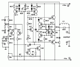
100W Audio Amplifier Transistor used BDW83D - BDW84D circuit diagram

100W Audio Amplifier Transistor used BDW83D - BDW84D circuit diagram         

Here 100 watt power audio amplifier which using power transistor BDW83D and BDW84D. Copyright belong to Smart Kit.


Component part list:

R1 = 1,2 K                                   D1 = 1N4002-7  
R2 = 0,47 OHM                           D2 = 1N2002-7  
R3 = 220 OHM                            D3 =  1N4148     
R4 = 3,9 K                                   D4 = 1N4148      
R5 = 2,2 K                                   D5 = 1N4148      
R6 = 2,2 K                                    D7 = 1N4148     
R7 = 10 K                                    D8 = 1N4148      
R8  = 4,7 K                                  Q1 = BDW84D   
R9 = 150 OHM                            Q2 = BD829       
R10 = 39 OHM                            Q3 = BC546       
R11 = 3,3 K                                  Q4 = BC556      


20 WATT FLUORO INVERTER used tip3055

20 WATT FLUORO INVERTER used tip3055
This circuit will drive a 40 watt fluoro or two 20watt tubes in series.
The transformer is wound on a ferrite rod 10mm dia and 8cm long.
The wire diameters are not critical but our prototype used 0.61mm wire for the primary and 0.28mm wire for the secondary and feedback winding.
Do not remove the tube when the circuit is operating as the spikes produced by the transformer will damage the transistor.
The circuit will take approx 1.5amp on 12v, making it more efficient than running the tubes from the mains. A normal fluoro takes 20 watts for the tube and about 15 watts for the ballast.
source : http://talkingelectronics.com/projects/200TrCcts/200TrCcts.html

Tuesday, April 20, 2010

SAMSUNG LE32A430 user guide

Precautions When Displaying a Still Image
A still image may cause permanent damage to the TV screen.
•   Do not display a still image on the LCD panel for more than 2 hours as it can cause screen
image retention.
This image retention is also known as "screen burn".  
To avoid such image retention, reduce the degree of brightness and contrast of the screen
displaying a still image.
•      Watching the LCD TV in 4:3 format for a long period of time may leave traces of
borders displayed on the left, right and center of the screen caused by the differen
of light emission on the screen. Playing a DVD or a game console may cause a si
effect to the screen. Damages caused by the above effect are not covered by the Warranty.
•   Displaying still images from Video games and PC for longer than a certain period of time m
produce partial after-images.
To prevent this effect, reduce the ‘brightness’ and ‘contrast’ when displaying still images.

download SAMSUNG LE32A430 user guide
key word :

samsung le32a430
samsung le 32a430

SAMSUNG LE32A430 user guide

Sunday, April 18, 2010

Testing a Triac

Testing a Triac


These two testing procedures are for use with a digital multimeter in the Ohm's test-range. Testing procedure was actually designed for testing inside micro-waves (magnetrons), but should be no difference in any other circuit. Test in- or out circuit.

A Triac is an electronic switch or relay. Triacs come in many shapes, sizes, and colors. Check the standard terminal designations in the picture below which shows most of the types of triacs that are commonly used in microwave ovens, along with their standard terminal designations.

Located either externally or fixed within an appliance or equipment, the triac operates when it receives an electronics "gate" signal from the control circuitry. It then switches to its closed or "on" state, thus providing for example, a voltage path to the primary winding of the H.V. transformer in a microwave oven and so activating the cooking controls. Or used in a laboratory water-bath which needs to be kept on a specific temperature. The probe-sensor, which is immersed in the water, keeps track of the temperature and sends a gate signal to the triac to either switch on the heating or cooling elements. Most of these probe sensors only contain one or more diodes of the general 1N4148 or 1N914 types.

more info

source : http://www.sentex.ca/~mec1995/gadgets/triactst.htm

TRIAC Light Controller

TRIAC Light Controller


Description
This project is intended for controlling mains powered disco lighting, although there are many other possible uses for controlling almost any mains appliance. It will control five seperate channels at up to 3 Amp per channel. This could be increased by designing another PCB with wider tracks than the PCB included with this design. I could have used relays to control my lights, but triacs seemed like a more sensible solution as they react quicker and are totally silent as they contain no mechanical parts. The low voltage control side and the mains side are totally isolated, as opto-couplers are used to fire the triacs. I have not included any schematics as this project is very simple, expecially due to the fact I have included a PCB.

more info 

Friday, April 16, 2010

LM4844 datasheet

Stereo 1.2W Audio Sub-System with 3D Enhancement
LM4844 datasheet
Description


The LM4844 is an integrated audio sub-system designed for stereo cell phone applications. Operating on a 3.3V supply, it combines a stereo speaker amplifier delivering 495mW per channel into an 8Ω load and a stereo OCL headphone amplifier delivering 33mW per channel into a 32Ω load.

It integrates the audio amplifiers, volume control, mixer, power management control, and National 3D enhancement all into a single package. In addition, the LM4844 routes and mixes the stereo and mono inputs into 10 distinct output modes. The LM4844 is controlled through an I 2C compatible interface.

Boomer audio power amplifiers are designed specifically to provide high quality output power with a minimal amount of external components.

The LM4844 is available in a very small 2.5mm x 2.9mm 30-bump micro SMD (TL) package.


Features


• Stereo speaker amplifier
• Stereo OCL headphone amplifier
• Independent Left, Right, and Mono volume controls
• National 3D enhancement
• I 2C compatible interface
• Ultra low shutdown current
• Click and Pop Suppression circuit
• 10 distinct output modes

Applications


• Cell Phones
• PDAs
• Portable Gaming Devices
• Internet Appliances
• Portable DVD, CD, AAC, and MP3 Players

download LM4844 datasheet

LM4755 datasheet

Description


The LM4755 is a stereo audio amplifier capable of delivering 11W per channel of continuous average output power to a 4Ω load or 7W per channel into 8Ω using a single 24V supply at 10% THD+N. The internal mute circuit and pre-set gain resistors provide for a very economical design solution.

Output power specifications at both 20V and 24V supplies and low external component count offer high value to consumer electronic manufacturers for stereo TV and compact stereo applications. The LM4755 is specifically designed for single supply operation.
 
Features


• Drives 4Ω and 8Ω loads
• Integrated mute function
• Internal Gain Resistors
• Minimal external components needed
• Single supply operation
• Internal current limiting and thermal protection
• Compact 9-lead TO-220 package
• Wide supply range 9V - 40V
 
 
Key Specification


• Output power at 10% THD with 1kHz into 4Ω at VCC = 24V:  11W (typ)

• Output power at 10% THD with 1kHz into 8Ω at VCC = 24V:  7W (typ)

• Closed loop gain: 34dB (typ)

• PO at 10% THD+N @ 1kHz into 4Ω single-ended TO-263 package at VCC=12V: 2.5W (typ)

• PO at 10% THD+N @ 1kHz into 8Ω bridged TO-263 package at VCC=12V: 5W (typ)
 
Applications


• Stereos TVs
• Compact stereos
• Mini component stereos
download lm4755 datasheet

Privacy Policy for free-schematic.blogspot.com

Privacy Policy for free-schematic.blogspot.com


If you require any more information or have any questions about our privacy policy, please feel free to contact us by email at elmanysat2010 [at] gmail.com or better contact us
At free-schematic.blogspot.com , the privacy of our visitors is of extreme importance to us. This privacy policy document outlines the types of personal information is received and collected by free-schematic.blogspot.com and how it is used.

Log Files

Like many other Web sites, free-schematic.blogspot.com makes use of log files. The information inside the log files includes internet protocol ( IP ) addresses, type of browser, Internet Service Provider ( ISP ), date/time stamp, referring/exit pages, and number of clicks to analyze trends, administer the site, track user’s movement around the site, and gather demographic information. IP addresses, and other such information are not linked to any information that is personally identifiable.

Cookies and Web Beacons

free-schematic.blogspot.com does use cookies to store information about visitors preferences, record user-specific information on which pages the user access or visit, customize Web page content based on visitors browser type or other information that the visitor sends via their browser.

DoubleClick DART Cookie

.:: Google, as a third party vendor, uses cookies to serve ads on free-schematic.blogspot.com.

.:: Google's use of the DART cookie enables it to serve ads to users based on their visit to free-schematic.blogspot.com and other sites on the Internet.

.:: Users may opt out of the use of the DART cookie by visiting the Google ad and content network privacy policy at the following URL - http://www.google.com/privacy_ads.html

Some of our advertising partners may use cookies and web beacons on our site. Our advertising partners include Google Adsense

These third-party ad servers or ad networks use technology to the advertisements and links that appear on free-schematic.blogspot.com send directly to your browsers. They automatically receive your IP address when this occurs. Other technologies ( such as cookies, JavaScript, or Web Beacons ) may also be used by the third-party ad networks to measure the effectiveness of their advertisements and / or to personalize the advertising content that you see.

free-schematic.blogspot.com has no access to or control over these cookies that are used by third-party advertisers.

You should consult the respective privacy policies of these third-party ad servers for more detailed information on their practices as well as for instructions about how to opt-out of certain practices. free-schematic.blogspot.com 's privacy policy does not apply to, and we cannot control the activities of, such other advertisers or web sites.


If you wish to disable cookies, you may do so through your individual browser options. More detailed information about cookie management with specific web browsers can be found at the browsers' respective websites.

Monday, April 12, 2010

3V Sweeping Siren Alarm

A while back I was challenged by a visitor to the website. He needed a very loud sweeping siren type audio sound generator powered by 3v. He tried some of the commercial sirens but they were not very loud when powered by 3v. He also said that those devices demanded much higher current than he wanted to use. I gave this problem some thought and came up with a design below.
The circuit uses a LTC1799 precision frequency generator from Linear Technology. A 74HC14 hex Schmitt trigger from Texas Instruments is also used to perform several other functions. One section is wired as a simple 7Hz square wave oscillator. The triangle waveform across that capacitor generates the low frequency sweeping signal for the siren. Two resistors bias the LTC1799 for a center frequency of about 2KHz. A flyback DC to DC converter circuit, produces a 40v peak signal, which is turned on and off according to the output of the LTC1799.
The output is connected to a quality piezoelectric beeper, which has a resonant frequency of about 2.5KHz. The result is a siren which is quite loud but draws only 40ma from a 3v supply. A piezoelectric device from Kobitone, part number 254-PB515-ROX, (Mouser part number 245-PB516) shown above works well. If you want something much smaller, although not quite as loud, try the Murata PKM17EPP-2002-BO shown above (Digikey part number 490-4688).

Click on Schematic below to view PDF version of this Circuit

                                                                       3v-SweepingSiren

Thursday, April 8, 2010

Tips how to cut Local Area Network LAN

1.using netcut software, dont even try to cut your server ip and yours, or you will be disconnected
2. winarpattacker, scan the connected network and choose the target
2.baned gateway
3. flooding
that's all maybe it is can help you

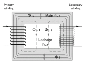
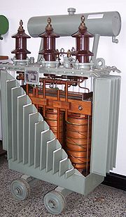
Tap Changer (Perubah Tap) Pada Transformator

Tap changer adalah alat perubah perbandingan transformasi untuk mendapatkan tegangan operasi sekunder yang lebih baik (diinginkan) dari tegangan jaringan / primer yang berubah-ubah.

Untuk memenuhi kualitas tegangan pelayanan sesuai kebutuhan konsumen (PLN Distribusi), tegangan keluaran (sekunder) transformator harus dapat dirubah sesuai keinginan. Untuk memenuhi hal tersebut, maka pada salah satu atau pada kedua sisi belitan transformator dibuat tap (penyadap) untuk merubah perbandingan transformasi (rasio) trafo.

Ada dua cara kerja tap changer:
1. Mengubah tap dalam keadaan trafo tanpa beban. Tap changer yang hanya bisa beroperasi untuk memindahkan tap transformator dalam keadaan transformator tidak berbeban, disebut “Off Load Tap Changer” dan hanya dapat dioperasikan manual (Gambar 1).

2. Mengubah tap dalam keadaan trafo berbeban. Tap changer yang dapat beroperasi untuk memindahkan tap transformator, dalam keadaan transformator berbeban, disebut “On Load Tap Changer (OLTC)” dan dapat dioperasikan secara manual atau otomatis (Gambar 2).

Transformator yang terpasang di gardu induk pada umumnya menggunakan tap changer yang dapat dioperasikan dalam keadaan trafo berbeban dan dipasang di sisi primer. Sedangkan transformator penaik tegangan di pembangkit atau pada trafo kapasitas kecil, umumnya menggunakan tap changer yang dioperasikan hanya pada saat trafo tenaga tanpa beban.

OLTC terdiri dari :
1. Selector Switch
2. diverter switch
3. transisi resistor

Untuk mengisolasi dari bodi trafo (tanah) dan meredam panas pada saat proses perpindahan tap, maka OLTC direndam di dalam minyak isolasi yang biasanya terpisah dengan minyak isolasi utama trafo (ada beberapa trafo yang compartemennya menjadi satu dengan main tank).

Karena pada proses perpindahan hubungan tap di dalam minyak terjadi fenomena elektris, mekanis, kimia dan panas, maka minyak isolasi OLTC kualitasnya akan cepat menurun. tergantung dari jumlah kerjanya dan adanya kelainan di dalam OLTC.

Semoga bermanfaat, HaGe.

Proses Terjadinya Busur Api Pada Circuit Breaker

Pada waktu pemutusan atau penghubungan suatu rangkaian sistem tenaga listrik maka pada PMT (circuit breaker) akan terjadi busur api, hal tersebut terjadi karena pada saat kontak PMT dipisahkan , beda potensial diantara kontak akan menimbulkan medan elektrik diantara kontak tersebut, seperti ditunjukkan pada gambar dibawah.

Arus yang sebelumnya mengalir pada kontak akan memanaskan kontak dan menghasilkan emisi thermis pada permukaan kontak. Sedangkan medan elektrik menimbulkan emisi medan tinggi pada kontak katoda (K). Kedua emisi ini menghasilkan elektron bebas yang sangat banyak dan bergerak menuju kontak anoda (A). Elektron-elektron ini membentur molekul netral media isolasi dikawasan positif, benturan-benturan ini akan menimbulkan proses ionisasi. Dengan demikian, jumlah elektron bebas yang menuju anoda akan semakin bertambah dan muncul ion positif hasil ionisasi yang bergerak menuju katoda, perpindahan elektron bebas ke anoda menimbulkan arus dan memanaskan kontak anoda.

Ion positif yang tiba di kontak katoda akan menimbulkan dua efek yang berbeda. Jika kontak terbuat dari bahan yang titik leburnya tinggi, misalnya tungsten atau karbon, maka ion positif akan akan menimbulkan pemanasan di katoda. Akibatnya, emisi thermis semakin meningkat. Jika kontak terbuat dari bahan yang titik leburnya rendah, misal tembaga, ion positif akan menimbulkan emisi medan tinggi. Hasil emisi thermis ini dan emisi medan tinggi akan melanggengkan proses ionisasi, sehingga perpindahan muatan antar kontak terus berlangsung dan inilah yang disebut busur api.


Untuk memadamkan busur api tersebut perlu dilakukan usaha-usaha yang dapat menimbulkan proses deionisasi, antara lain dengan cara sebagai berikut:

1. Meniupkan udara ke sela kontak, sehingga partikel-partikel hasil ionisai dijauhkan dari sela kontak.
2. Menyemburkan minyak isolasi kebusur api untuk memberi peluang yang lebih besar bagi proses rekombinasi.
3. Memotong busur api dengan tabir isolasi atau tabir logam, sehingga memberi peluang yang lebih besar bagi proses rekombinasi.
4. Membuat medium pemisah kontak dari gas elektronegatif, sehingga elektron-elektron bebas tertangkap oleh molekul netral gas tersebut.

Jika pengurangan partikel bermuatan karena proses deionisasi lebih banyak daripada penambahan muatan karena proses ionisasi, maka busur api akan padam. Ketika busur api padam, di sela kontak akan tetap ada terpaan medan elektrik. Jika suatu saat terjadi terpaan medan elektrik yang lebih besar daripada kekuatan dielektrik media isolasi kontak, maka busur api akan terjadi lagi.

Semoga bermanfaat, HaGe.

Wednesday, April 7, 2010

Small Single Chip FM Transmitter Circuit Schematic Diagram

Small Single Chip FM Transmitter Circuit Schematic Diagram

The following circuit schematic diagram is the one used for the monophonic FM Transmitter. It is pretty clear seen on the circuit’s schematic that the left and the right signal is mixed before modulate the radio frequency.


Maxim Semiconductor’s MAX2606 is the core of this circuit. It is an integrated circuit which is compact, high-performance intermediate frequency voltage controlled oscillators. The output from this circuit is -21 dBm radiation power, and work with 3 volts power supply, so two small batteries with 1.5 volts each should be enough. You just only need a potentiometer to tune in the frequency within commercial FM broadcast band 88-108 MHz. And that is the best part. The frequency tuning circuitry have been handled by the IC, so you don’t need to bother. External varactor even doesn’t need in this circuit. One of the application that can be used with this circuit, you can extend your mp3/CD player in your room to your portable set around the house. Much more simple than using wires. [Source : Maxim Integrated Products Application Notes]

Audio Amplifier Circuit using uPC1318AV

Audio Amplifier Circuit using uPC1318AV

Audio Amplifier Circuit using STK083

Audio Amplifier Circuit using STK083

STK083 Audio Amplifier Circuit

Circuit diagram 500mW FM PLL transmitter 88-108MHz using LMX3206 – PIC16F870

Circuit diagram 500mW FM PLL transmitter 88-108MHz using LMX3206 – PIC16F870

Circuit diagram 500mW FM PLL transmitter 88-108MHz


500mW PLL FM transmitter 88-108MHz
This PLL transmitter is controlled and the frequency is very stable and can be programmed digitally.
Transmitter will work 88-108 MHz and output power up to 500mW.
With a small change can set the frequency of 50-150 MHz.

The output power is often set to several watts with transistors.
So therefore I decided to build a simple transmitter with great performances.
The frequency of this transmitter can easily be changed by software and space / compress air coil.
This transmitter is the oscillator colpitts. Oscillator is a VCO (voltage controlled oscillator) which is set by the PLL circuit and PIC micro controller.


This oscillator is called the Colpitts oscillator and voltage controlled to achieve the FM (frequency modulation) and PLL control. T1 must be HF transistors to work well, but in this case I use a cheap and common BC817 transistor. LC tank oscillator needs to oscillate properly.
In this case the LC tank consists of L1 with the C1, C2, C3, and varicap BB139.
Coil parallel to the C1 and C2 in series. The same with the varicap and C3.
You may think that L is parallel to the [(C1 / / C2) + (Varicap / / C3)]
C3 will determine the value range VCO. Large value of C3 will be broader in the range VCO can be.

PLL and Microcontroller


Oscillator is made to work as a “Voltage Controlled Oscillator” VCO.
To control the frequency synthesizer circuit LMX 2306 has been added. The PLL circuit has a pickup coil (L2) is connected to pin 6.
This coil should be placed close to the coil L1 to take some of the energy oscillates.
The LMX2306 PLL in to use this frequency to adjust and lock the VCO to the desired frequency.
Systems also need to set the external reference crystal. In this case I use 12.8 MHz.
 pin2 of MX2306 you will find the PLL filter to form a VM that is set voltage of the VCO.
The PLL tries to arrange so that the oscillator frequency Fout kept locked to the desired frequency.
The desired frequency programmed into the PIC EEPROM and clocked into the synthesizer (LMX2306) at power up.
I will below explain how to program the EEPROM to different frequencies.
In the pin14 of your synthesizer control output. In this output you will find a reference frequency for testing.

(I must warn you that the signal is not symmetrical in form. Pulsa positive only a few microseconds, so you will be hard to see on the oscilloscope.) I solved by connecting it to 74HC4020 (14-stage Binary Counter) to input pin 10 Hours. In Q0 (pin 9) you will have a symmetrical square wave with a frequency half since the circuit is a table. In Q1 pin 7 will be divided by 4, see data sheet for more information.

LF input
You want to send audio must be connected to the audio input (left schematic).
Will affect the signal and thus modulate the FM varicap RF carrier frequency.
A potentiometer P1 was added to adjust the depth of modulation (FM Wide or Narrow FM). You may have to play a bit with a value of P1 because it tends to modulate the lot. You may need to add the 500k – 1M potentiometer only. You test and find out for himself.

Buffer stage
Here you find other HF transistors and work in the class C.
Resistor R1 and resistor Re2 regulate the flow of DC. In this case I find that 9.1k will give a good output power and thus equal to 150. If you want to increase the power should be lower Re2. You can add another 150 ohm resistor in parallel.
In the table below I’ll show the output power with different voltages and resistor values of Re2.
I advice you to not run the transmitter with a high output power. Transistor I use is small and tends to be hot.
I advice you to run the unit from the 0 – to 200mW. At the transistor will 500mW pain …* smiles *
At the output you will find a network T. This “filter” will match the transmitter to the antenna impedance output stage.
You have two variables 60pF capacitors to tune the transmitter for best performance.
The antenna I use I a 1 / 4 wave whip antenna (wire) about 75cm long.
Smaller antenna types, but not so good performance as a dipole.
With a dipole you will be more long distance transmitter.
How long can I pass?
It is a very difficult question because the environment affects the transmission distance is very much.
In a city environment with concrete buildings transmitter will send maybe 200m.
I will send a proposed open 2000m.
I did the test and filed with 70mW output power into a “bad” whip antenna is placed in the room I can send 200-300m to a park without a problem.
Sunday, April 4, 2010

Understanding FM transmitter circuit

Understanding FM transmitter circuit

Hi,


I'm trying to understand how the following FM transmitter circuit works. I got it from the site

Wireless FM Transmitter. The site has some explanation on how the circuit works, however I'm not sure about a few things, including the electret mic & how the frequency modulation takes place.
The electret microphone has a current of 200uA which changes by +- 3 uA depending on sound waves. This sets the voltage across R1 to 2V and the voltage across the mic to 4 volts. As the sound hits the mic the current through R1 increases slightly reducing the voltage across the mic. Is that what is happening?

This changing voltage is passed on by the coupling cap, C1 to the base of the transistor, which is biased by R2 & R3 to approx 2V. The voltage across R4 with no signal on the mic will be Vb - 0.7 (drop across vbe), 1.3 volts. As the voltage at b changes R4 will change by the same amount. This change in voltage is seen at the base of the tank circuit. And the signals voltage is increased/decreased. Isn't this what happens in AM? As wouldn't the capacitance need to change in order to get Frequency modulation? And if it was amplitude modulation occuring in the FM spectrum, then how would a radio receiver be able to demodulate the signal?

At this point I'm not sure what is happening at the capacitor C3, what is that doing? Is it holding CE at a fixed voltage? And is it along with capacitor C2 considered a bypass capacitor? Or do bypass capacitors need to be connected to ground?

2×25W Stereo Power Amplifier with STK4141II

2×25W Stereo Power Amplifier with STK4141II

Here the stereo power amplifier based on single IC STK4141II. This amplifier circuit will deliver 25W on each output channel.
Recommended voltage is 27.5V for 8ohms speaker and 24.5V for 4ohms speaker while the maximum voltage to supply this circuit should be about 41 VDC.

Heatsink usage on the power IC is a must.

Use this STK4141II Datasheet for your reference.
 
download

Saturday, April 3, 2010

Electric Niccan leaf car

New electric Car from Nissan named Nissan leaf . powered by 100 electric source

Classic deviled eggs recipe

Tecipe to create Classic deviled eggs recipe, perfect for post-Easter and summer picnic potlucks. Mashed cooked egg yolks, mixed with mayonnaise and Dijon, spooned or piped

Friday, April 2, 2010

vga pinout

vga pinout

vga pinout
1 - red out                                   6 - red return (ground)
2 - green out                                 7 - green return (ground)
3 - blue out                                  8 - blue return (ground)
4 - unused                                    9 - no pin
5 - ground                                    10 - sync return (ground)

11 - Monitor ID Bit 0

12 - monitor id 1 in or data from display

13 -horizontal sync out

14 - vertical sync

15 - monitor id 3 in or data clock

Thursday, April 1, 2010

1.5V LED FLASHER CIRCUIT

1.5V LED FLASHER CIRCUIT

1.5V LED FLASHER CIRCUIT
AVERAGE CURRENT = 120uA
PEAK LED CURRENT = 20mA
4mS PULSE  1 FLASHE/SEC
APPROX. 6 MONTHS OPPERATION FROM N-CELL
APPROX. 12 MONTHS OPPERATION FROM AA CELL

DAVID JOHNSON AND ASSOCIATES


MINIATURE LED FLASHING CIRCUIT

1.5 VOLT CIRCUIT

lm3909 led flasher

lm3909 led flasher

LM3909 LED Flasher Oscillator


General Description

The LM3909 is a monolithic oscillator specifically designedto flash Light Emitting Diodes By using the timing capacitor

for voltage boost it delivers pulses of 2 or more volts to the LED while operating on a supply of 1 5V or less The circuit is inherently self-starting and requires addition of only a battery and capacitor to function as an LED flasher

Packaged in an 8-lead plastic mini-DIP the LM3909 will operate over the extended consumer temperature range of b25 C to a70 C It has been optimized for low power drain and operation from weak batteries so that continuous operation life exceeds that expected from battery rating

Application is made simple by inclusion of internal timing resistors and an internal LED current limit resistor As shown in the first two application circuits the timing resistors supplied are optimized for nominal flashing rates and minimum power drain at 1 5V and 3V

Timing capacitors will generally be of the electrolytic type and a small 3V rated part will be suitable for any LED flasher

using a supply up to 6V However when picking flash rates it should be remembered that some electrolytics have very broad capacitance tolerances for example b20% to a100%


Features


Y Operation over one year from one C size flashlight cell

Y Bright high current LED pulse

Y Minimum external parts

Y Low cost

Y Low voltage operation from just over 1V to 5V

Y Low current drain averages under 0 5 mA during
battery life

Y Powerful as an oscillator directly drives an 8X speaker

Y Wide temperature range

Applications

Y Finding flashlights in the dark or locating boat mooring
floats

Y Sales and advertising gimmicks

Y Emergency locators for instance on fire extinguishers

Y Toys and novelties

Y Electronic applications such as trigger and sawtooth
generators

Y Siren for toy fire engine (combined oscillator speaker driver)

Y Warning indicators powered by 1 4V to 200V